Moto Morini Club Nederland
GENERAL TECHNICAL INFORMATION
Moto Morini V-twins (350/250/500cc) and (125/250cc) singles
timing belt, electronic ignition, pick-up, alternator, electronic rectifier
|
Table of content of this page:
|
- Electronic ignition system (Ducati Elettrotecnica), OEM on Moto Morini
- Definitions of the ignition parts
- Different versions of parts
- A table of matching ignition parts (pick-up & transducers)
- Transducers, self-build, repair, replacement
- Lucas Rita, alternative system
- Bransden, alternative system
- Vape (former Power Dynamo - also known as "MZ-b"), alternative systems for both 3˝ V-twin and also
the 175cc singles (like/similar to 175 GT 175 Tresette, etc.) and the Corsaro 125/150cc
- Digital ignition for both 3˝ and 500 V-twins, alternative system
- Nuovaray, many parts for the original ignition
- Horse Power Ignition, for the 125/250/350/500cc models. Also sets available for the 175cc singels and Corsaro 125/150cc.
|
|
- German article on the various pick-ups (by Franz Grabowski) and information on the ignition curve
(by Gunnar Lerch), in both English and German
|
|
|
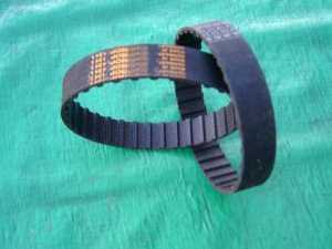
THE MORINI TIMING BELT
Replacement of the Morini timing belt should not be a real problem. The belt is commonly used in industry.
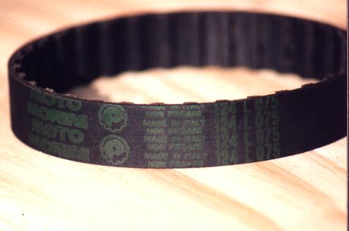
Print on an original Pirelli belt from left to right (see photo's below):
- Moto Morini;
- styled "P" of "Pirelli", sometimes Isoran/Pirelli is printed;
- made in Italy;
- 124L075. This is the size. 124 means length: 12,4 inch, 075 stands for width 0,75 inch and
L means you'll find teeth on the inside only. If it would say "XL", then you would have a
belt with teeth on both inside and outside;
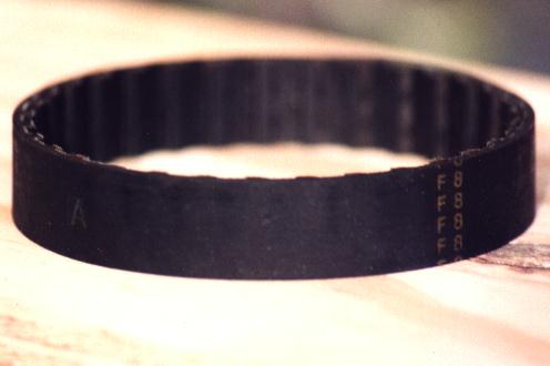
- A, refers to the (sub)size. You can find three types: A, B or C belts, from Pirelli that is.
These letters refer to the production tolerance. The metal toothed cam in the engine, on which the belt
is placed has got an A, B or C stamped at the factory. By means of measurement a match was made in the
factory between top and bottom cam and the tolerance was set. The A, B or C belt versions each differ
0,3 mm in length.
- F8, production month and -year in the 80s, 90s. "F" stands for June and "8" means 1988.
Remarks:
- The series of belts E2 up to D4
(May '82 until April '84) were called back by the factory at the time,due to a faulty production, but this factory notice did
not reach outside Italy.
- Difference between the original Pirelli, made for Morini and other makes, all made to DIN (German Industry Norm) is that
the teeth of the Pirelli belts are 0,1 mm higher.
- Fitting of a non-original belt made by Gates or Continental, or others can cause
problems: too tight or too loose. A friend of mine had a too tight belt, which
produced smoke & stink, after fitting. Someone else could take a non-original
belt off both cams by just holding it between two fingers.
- Please note:
Some people have reported hearing louder bearing noise (probably from the right-side cam bearing) after installing a new cam
belt, even if the belt tension is within specifications. Sometimes, fitting a
belt which is not too tight will eliminate the noise.
How long will the belt last?
That's important of course. You should replace the belt from time to time, to prevent trouble. The original Pirellis should
last between 12,000 and 15,000 km's, or after a maximum of 36 months of use. If you would not use your bike at all, you would still
have to replace the belt, because the material gets older and dries out. A German technician once found out that the forces, which
work on these belts are twice as much as what they are designed for, accoring to the German Industry Norm (DIN). So it makes sense
to replace this part from time to time. My own bike has an "A" in both metal cams. I have replaced the original Pirelli
belt successfully by a Mitsuboshi one. From time to time I have checked the Mitsuboshi replacement belt and it seems to be right.
See the Mitsuboshi site on their products and applications.
Different makes
Pirelli still produces the original Morini replacement belts, but also other factories
like Continental, Gates and Mitsuboshi produce them. These "nylon"/rubber belts, which might
even have kevlar added, are also used for other industrial machines and not just in Morini
engines. So next time, at the baker's, have a look inside the machine that slices up the
bread. You never know, you could find a "124L075" belt ;-))
|
 |
 |
 |
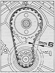
The Morini manual mentions
a slack of 6 mm for the timing
belt. That is too much. The belt
should have a tighter fit. |
Click for larger size.
The original Pirelli belt with
"Moto Morini" print. |
On the right "F8" is printed (month of
production) and an "A" (sub-size) can
be seen vaguely on the left. |
| A former secretary of the Dutch Morini Club gave me an example of a Gates belt, which he could, after 2,000km's,
take off with his fingers. This is no judgement on the Gates quality, but it does mean you have to be carefull with the right fitting.
Just imagine what would happen inside the engine if something went wrong, while changing gears. Don't forget, the bottom cam only makes
contact with the belt on 4 to 5 teeth. The former secretary recently experienced (with a Mitsuboshi belt), that after 16,000 km's the
fitting of it was still better, than the new one he was going to fit (too loose). This had to do with the tolerance of the production.
On Mitsuboshi belts, you won't find the A, B or C type belts as from Pirelli. So if a Mitsuboshi does not fit well, too tight or too
loose, try another one from a different lot. Easier said than done of course, because once you have bought one, I don't think a your
supplier would take it back. Most makes/brands should be petrol and oil proof, but it is worth to check this. My own local Morini dealer
sells a lot more Mitsuboshi belts, which makes them more "fresh'' and which will mean they will last longer. |
 |
| |
original belts |
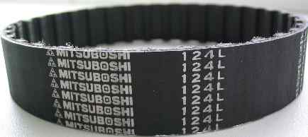 |
The print on the Mitsuboshi belt. |
Follow this link for a well illustrated site (in German) which
shows the belt replacement and also valve adjustment.
|
MORINI IGNITION SYSTEM
The Morini ignition: a pain in the ****?
Not necessary, if you read this article carefully :-)
|
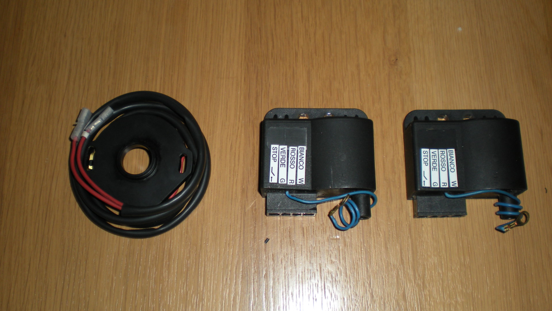
Definitions:
- TRANSDUCER - black or grey box under the fuel-tank. It consists of electronic components
and a coil all in the same housing. Warning: NEVER connect the battery to
the transducers, because this will blow them up;
- COIL - used in conventional ignitions in combination with a set of contacts.
In the transducers used by Morini, a coil is integrated. The coil works identical as a
transformer. A low voltage in the primary windings is transformed into a high voltage in
the secundary windings by induction. This high voltage creates a spark between the electrodes
of the sparkplug;
|
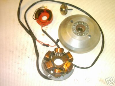 |
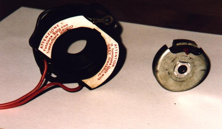
- PICK-UP - two (V-twin), or one (singles) coil(s) in a round red or black plastic housing,
situated on the left-hand-side of the engine, between both cylinders. In the middle a small magnet, which is fixed to
the cam-shaft, rotates and gives a signal to the transducers when to discharge
their built-up charge to the spark-plugs;
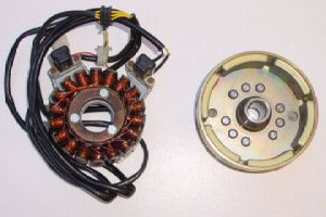
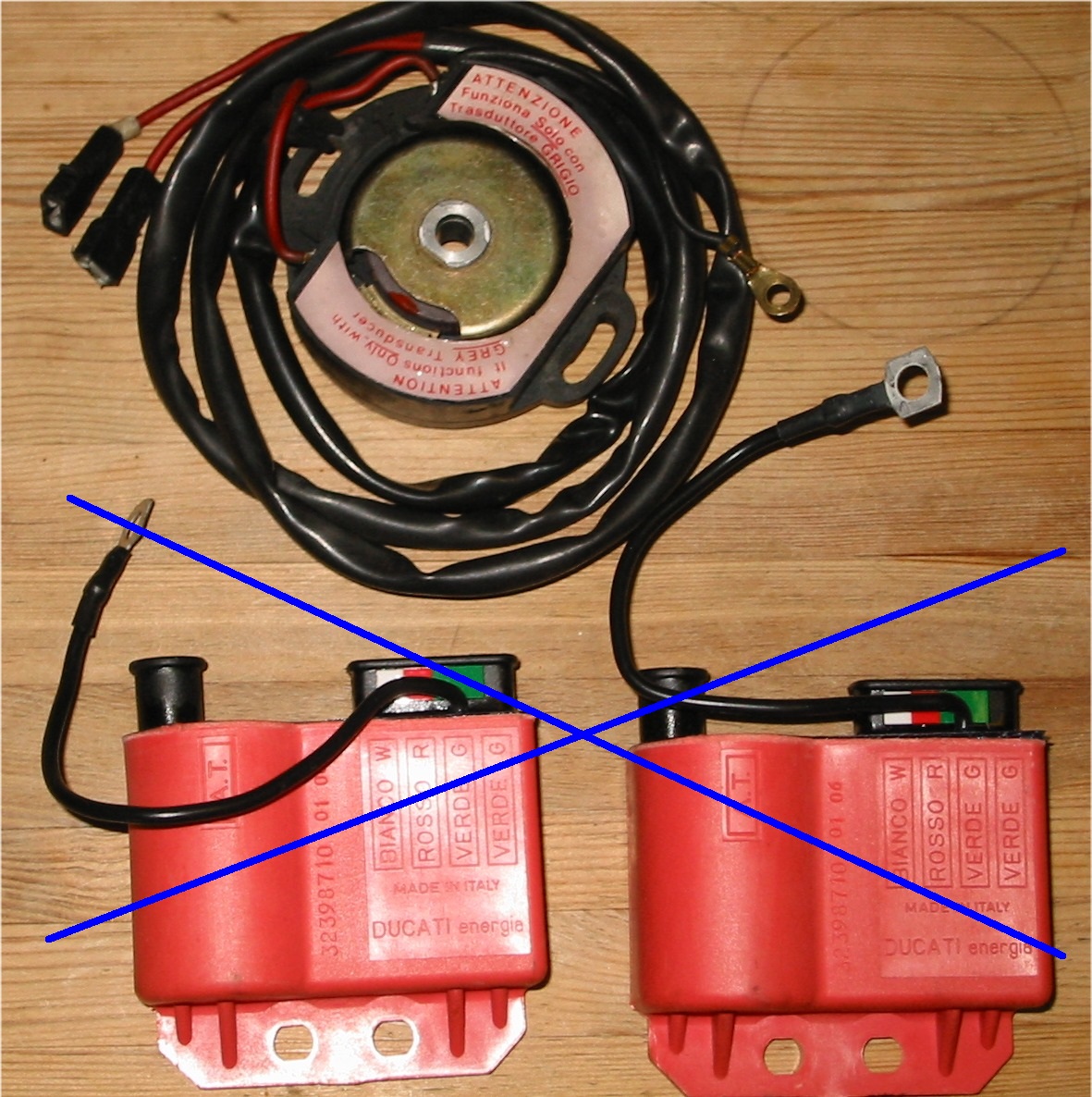
| clockwise: red pickup, pickup
magnet, flywheel, alternator.
(Transducers are missing on
this picture). |
- ALTERNATOR - both V-twin and single models have an alternator (produces alternating current).
The two yellow wires from the alternator are connected to the rectifier/regulator. In this article we will not
mention the regulator. Next, also a red and also a green wire come from the alternator. Some later models also
have a white wire. White is an earthwire (on earlier models the alternator has no seperate wire for earth).
The green wire is important for the ignition, as it is connected to the seperate (yellow) coil inside the
alternator, which "feeds" the transducers.
2 yellow wires: to rectifier;
1 green wire: from alternator/seperate yellow coil to fusebox and ignition switch;
1 red wire: to fusebox. (See below in this article).
- Note: the off-road models like Kanguro & Camel have a mixed 6V/12V system. 12V directly to
the headlight, 6V to a small battery for the rest of the electrical system. The 125cc & (250cc ?) bikes have
an electrical system of 6V.
- Warning: NEVER connect 6V or 12V directly to the transducers. It will destroy them permanently.
 |
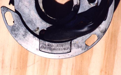 |
The alternator & flywheel.
Click on photo's for larger size. |
The back of the alternator with the name
of the producer "Ducati Elettrotecnica". |
 |
 |
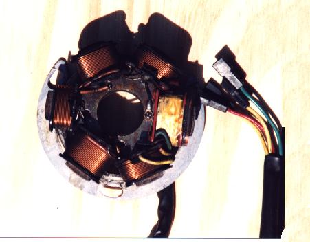
Another picture of the alternator/generator
with it's 4 wires: 2 yellow, 1 red, 1 green.
Between the metal mass of the generator
and green wire you should measure something
between 170 and 250 Ohm. In that case the
yellow ignition coil is OK.
(On several coils I measured 220 Ohm). |
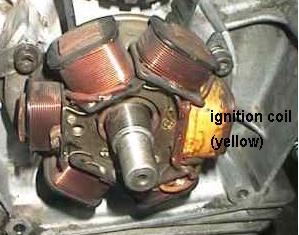
Photo of the alternator still on the bike.
The yellow coil is connected to the green wire. |
General
In general, in the Netherlands, Morini V-twins have not got a good name, both with the public as in bike-shops. They are
supposed to be bikes, which always suffer some kind of trouble. Earlier this year, I heard three stories in a row about
various bike-shops where they had a Morini somewhere in a corner, which was "given up". Various attempts to get the engine
back alive had failed and the bikes were left with the hope one day a buyer would turn up. Also some members of the Dutch
Morini Club are not too happy with their V-twin.
Strange, when you think about the fact that the 3˝ in both Italy and England is known as a very reliable machine, which is
nearly "bullet-proof". In the Netherlands, many problems were caused by lack of knowledge and many bikes were never serviced
properly, because they were cheap. It is remarkable that 50% or more of problems with the Morini V-twins are caused by the
ignition. In the Netherlands there is little knowledge on the Morini ignition (made by "Ducati Elettrotecnica"). Even our
own newsletter Rebello has published little on this subject in the past.
Most that was written is already some time ago. So a good reason to publish this story. In the past I have learnt a lot on
the ignition, information I can share with you.
In case your ignition causes problems, first of all measure the electric resistance of the seperate coil in the
alternator, by taking off the green wire from the fuse box. Connect the green wire to an Ohm meter and connect the other
terminal of the Ohm meter to earth ( - ). You should measure something between 170 and 250 Ohm. On a number of alternators,
I have measured 220 Ohm for the ignition coil, so this is probably a normal value. In case the value is less than 170 Ohm,
the windings (or insulation) of the seperate coil for the ignition are/is broken and the coil should be re-wound, or the
alternator should be replaced.
 |
Different versions of ignition parts
First of all, I would like to give a description of the various versions of the
electronic ignition, as we know it from the V-twin models. Also I will mention the
ignition of the singles, like the 125 single ("half" of the 250 V-twin and 250 single
"half" of the 500 V-twin). There are big differences between the parts for the singles
and the V-twins and these differences can lead to big problems, in case you "mix" the
wrong parts.
The ignition as fitted by the factory (OEM), was built by Ducati Elettrotecnica. The quality of the
electronic ignition is good, but perhaps a little "under-sized". Some of the components could have been
a little more "over-sized" to last longer and also to give a stronger spark. Although the construction
of the transducers is simple, the technical theory is far from simple. A German technician by the name of
Franz Grabowski has published an article on the ignition pick-up. Elswhere on this page you can download this
excellent article (in Adobe .PDF format), but unfortunately it is in German and too complicated to translate
into English. You can take it from me that the pick-up is a simple, but well designed part of the ignition.
I don't think it is necessary to change the Ducati Elettrotecnica ignition of your Morini for an ignition of
another make. As the Morini V-twin models are getting older, more problems can be expected. Another problem is
that original replacement-transducers are no longer made. |
On the left: transducer of the first generation.
The red dot sticker indicates that it is of a Morini 500. On the
right a transducer of the third generation (with bulge). The second generation has the same shape as the first
generation but is grey of colour instead of black. |
Fortunately in the past few years professionally made replacement parts (f.i. a better than original pick-up) were
introduced, mostly in Germany. Even a digital system is worth mentioning. See on this page under alternative systems.
Basically you can stick to the original ignition. Even if original replacement parts are no longer made, parts are still
reasonable in price, compared to many modern bikes. The original ignition also has the excellent feature to retard the
ignition (and to prevent backfire when using the kickstarter), when the engine is started and also to advance the spark
timing above 6,000 rpm.
Different versions of transducers and pick-ups
Over the years Moto Morini used the Ducati Elettrotecnica system (all-in-all 3 different versions of transducers
and 3 different pick-up's). Later, on the bikes built under Cagiva management (>1986/7), the Japanese
Kokusan ignition, was introduced.
Bikes involved are: Excalibur, Dart, New York, Camel X3 and Coguaro (perhaps also Kanguro X3?). This ignition was
integrated in the alternator, which also housed the pick-up. So this last item was no longer fixed to the end of the
camshaft, as on previous models. This means that the cam-shafts of Excalibur, New York and Dart are probably
shorter and also that the end of the cranck shaft probably has a different shape. So on these models you can't
fix a Ducati ignition. On the earlier Morini's like the 3˝ and 500 you can't fix a Kokusan ignition. So keep this
in mind, in case you buy used parts from a breaker. |
 |
The very different Kokusan alternator.
It was used for the later V-twins, like Dart
350/400, Camel X3, Excalibur, New York and Coguaro. The black coils, on the photo above the alternator windings, are for the ignition. |
 |
 |
 |
 |
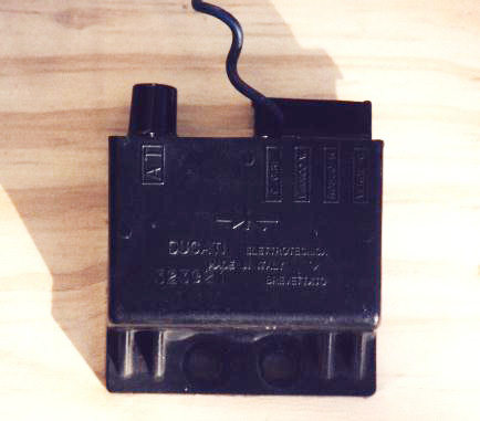
A close-up of a 1st generation black transducer, made by Ducati Elettrotecnica. Vaguely you can
see the number stamped in the plastic housing: 323921, which identifies it as a transducer for the 350. The green dot is missing. |
|
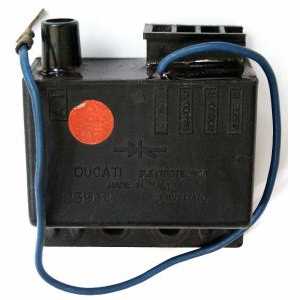
A close-up of a 1st generation black transducer, made by Ducati Elettrotecnica. The red dot identifies
it as a transducer for the Morini 500. See the number stamped in the plastic housing: 323934. |
|
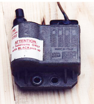
3rd generation grey transducer, with bulge. Note the sticker which states to use it only
in combination with a black pick-up. This particular transducer is made in Italy by Zanussi(!) |
|
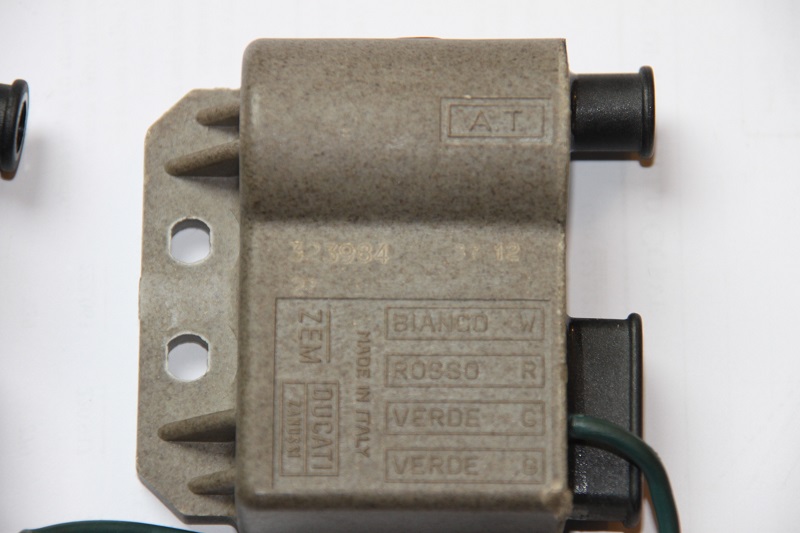
The 323984, or 3rd generation transducer for the 500cc. On a different picture (not on this page),
you can indeed see the red round stickers. Unfortunately the number is not very clear to see. It's on the lhs just under the horizontal
line of the bulge. Connection 'bianco' (white) is an extra earth. Of course, this grey type transducer should only be connected to a black pickup. |
Three series Ducati Elettrotecnica transducers
The ignitions of the 3˝, 500, 250 V-twins and also the 125 and 250 single consist
of three different series of transducers and also three different pick-up's (2 different
red ones and 1 black one).
Each model bike (125 single, 250 single, 250 V-twin, 350 V-twin and 500 V-twin) have
their own specific transducer(s), which differ from each other, because they have to create
a different advance of ignition. The 3˝ models have a maximum advance of 34o
and the 500 models have an advance of 30o.
The transducers of the first and second/third generation also differ,
because the first generation can only work properly with a red pick-up; the second/third
generation can only work with a black pick-up! The black pick-up has not got a set of
diodes, which are fixed inside the red pick-up. In the second and third series of transducers
this diode is fixed inside the transducer itself.
When you realise there were at least five different engines, each with three generations
transducers and different pick-up's the number of possible combinations is huge! The bad part
is all these different components can be combined and you will get the engine started on it,
but with the wrong combination transducer/pick-up, or two different transducers you will get
an engine of which the ignition will not advance, but will delay at certain revolutions
per minute. Another possibility is an engine in which the timing of only one cylinder is right.
With the wrong combination of ignition parts, the best scenario is the engine will produce more
vibration, in the worst scenario, the engine will break down (piston will seize, or a hole in
the piston).
SO IT IS IMPORTANT TO HAVE THE RIGHT COMBINATION IGNITION PARTS ON
YOUR BIKE AND TO CHECK THESE, BEFORE YOU START LOOKING IN CASE OF BREAK-DOWNS.
 |
 |
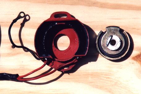
The black pick-up for the second and third
generation transducers. Mostly the sticker
is gone. |
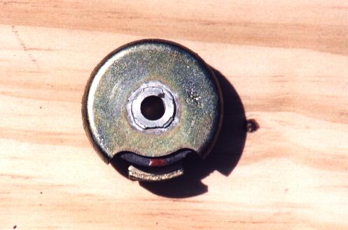
The matching magnet for the back pick-up,
identical to magnet for the 2nd red pick-up. |
- Three different sorts of transducers & three different red or black pick-up's (see also the table below):
- First series transducers, box-shaped black, connect a red pick-up.
- Second series of transducers, box-shaped grey, connect a black pick-up
(see photo above on the left).
- Third series of transducers, grey with a bulge (a heavier
coil was built inside), connect black pick-up.
- Two sorts of red pick-up's and a black one. Both types of red pick-up's & their matching magnets should be kept together
as a set, as the magnets cannot be swapped. Both types of red pick-up's work identically, but the angle between the metal spots,
which you can see through the potting, is different, and both magnets are different as well.
- The first (older) red pick-up.:
The older version has a magnet with a grey colour and it looks like it has been milled.
Also the name "Ducati-Elettrotecnica" has been written on it in very small letters. The matching
pick-up can be recognised by the soft metal parts of the coils inside. The soft-metal strips inside
have a width of ±13 mm.
- The second red pick-up.:
(used until ±1981) has a copper/golden colour magnet, which looks like it is made from a pressed piece
of metal. It has no writing on it. The soft-metal strips inside are ±7 mm wide. In case you would swap
the magnets of these red pick-ups, you will interfere the ignition timing badly. Both these red pick-ups
should be used with the black transducers (square boxes) only.
- The third and last type of pick-up's used by Morini is BLACK.:
The black pick-up originally has a sticker on it to only use it in
combination with grey transducers (2nd or 3rd generation) only. The magnet
of the black pick-up is identical to the magnet of the 2nd type red pick-up.
 |
 |
 |
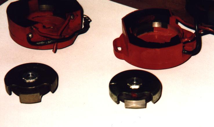
 |
On the left of this photo the first red pick-up, on the right the second red pick-up. Look at the difference of the internal coils
and the different magnets. |
Rearview of both second red pick-up and matching magnet. The magnet is identical to the one of the black pick-up.
Note: the diagonal black line is a shade from the sunlight. |
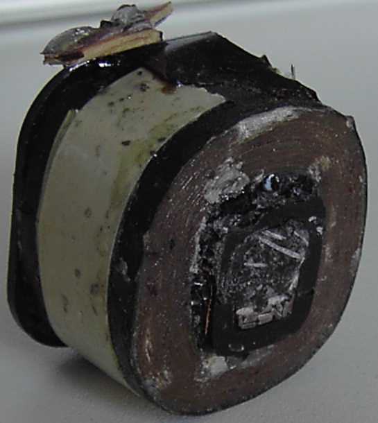
Cracked potting of a broken red pick-up. |
Inside the pick-up, 2 sets of these week iron plates can be found. The angle between both sets is very important and should be
72o, identical to the angle between both cilinders. If the angle is not exactely 72o, the timing of one of both cilinders will
never be correct.
Note 1: this set is from a black pick-up.
Note 2: around the week iron plates, a thin wire is wound. This way it changes into a coil. For further technical details on the pick-up:
read this article (in German). |
Tip 1: a common problem of the Morini ignition is to get it in phase. When the timing of the front cylinder is set
correctly, the rear cylinder can be slightly off-time. When you set the timing, based on the rear cylinder, the front
cylinder can be off-time slightly. This has to do with the position (towards each other) of the two sets
(see below in the In-Depth German article) of horseshoe shaped metal plates inside the pickup.
Pietro Ligorio has thought of a simple, but efficient method to correct this. (Another way to
correct the spot-on timing of both cylinders, is to use an aftermarket pickup, made by Marcus Heilig
(see below)).
Tip 2: Pietro Ligorio also drew a small electronic circuit to connect
an electronic rev. counter to a 3rd generation (grey) transducer. Normally this is impossible, as the grey transducers
do not have a connection for an electronic rev. counter. Bikes with these types of transducers were fitted with a mechanical
rev. counter. I have seen this small circuit integrated in a cable and hidden under the fueltank.
Tip 3: as I noticed myself a Morini 500 will start and run on the transducers and matching pick-up of a 3˝.
The difference in advance can easily be compensated by re-setting the ignition with a stroboscope. (The maximum advance
will be 30o again). A 3˝ with transducers and matching pick-up of a 500 is also possible. However, you
cannot/should not use two different transducers on one engine or a wrong transducer/pick-up/magnet combination.
| The numbers on the various transducers are as follows: |
| Transducers |
1stseries black, square |
2ndseries grey, square |
3rdseries grey, bulged |
Aftermarket
red, bulged
|
| 350 |
number 323921
(green sticker) |
number 323971
(green sticker) |
number 323982
(green sticker) |
number 323987
(see text below on availability) |
| pick-up |
red |
black |
black |
black |
| 500 |
number 323934
(red sticker) |
number 323974
(red sticker) |
number 323984
(red sticker) |
|
| pick-up |
red |
black |
black |
|
| 125H |
number 323921
(green sticker) |
|
|
|
| no pick-up, but a sensor in the alternator |
|
|
|
|
250T
(single) |
number 323931
(?? sticker) |
|
|
|
| pick-up |
red |
|
|
|
250V
(twin) |
number 323921
(?? sticker) |
|
|
|
| pick-up |
red |
|
|
|
250 2C
(1981) |
number 323921
(green sticker) |
|
|
|
| pick-up |
?? |
|
|
|
As you see, we don't know all the numbers of the smaller models. If you can tell us more, please e-mail
the webmaster.
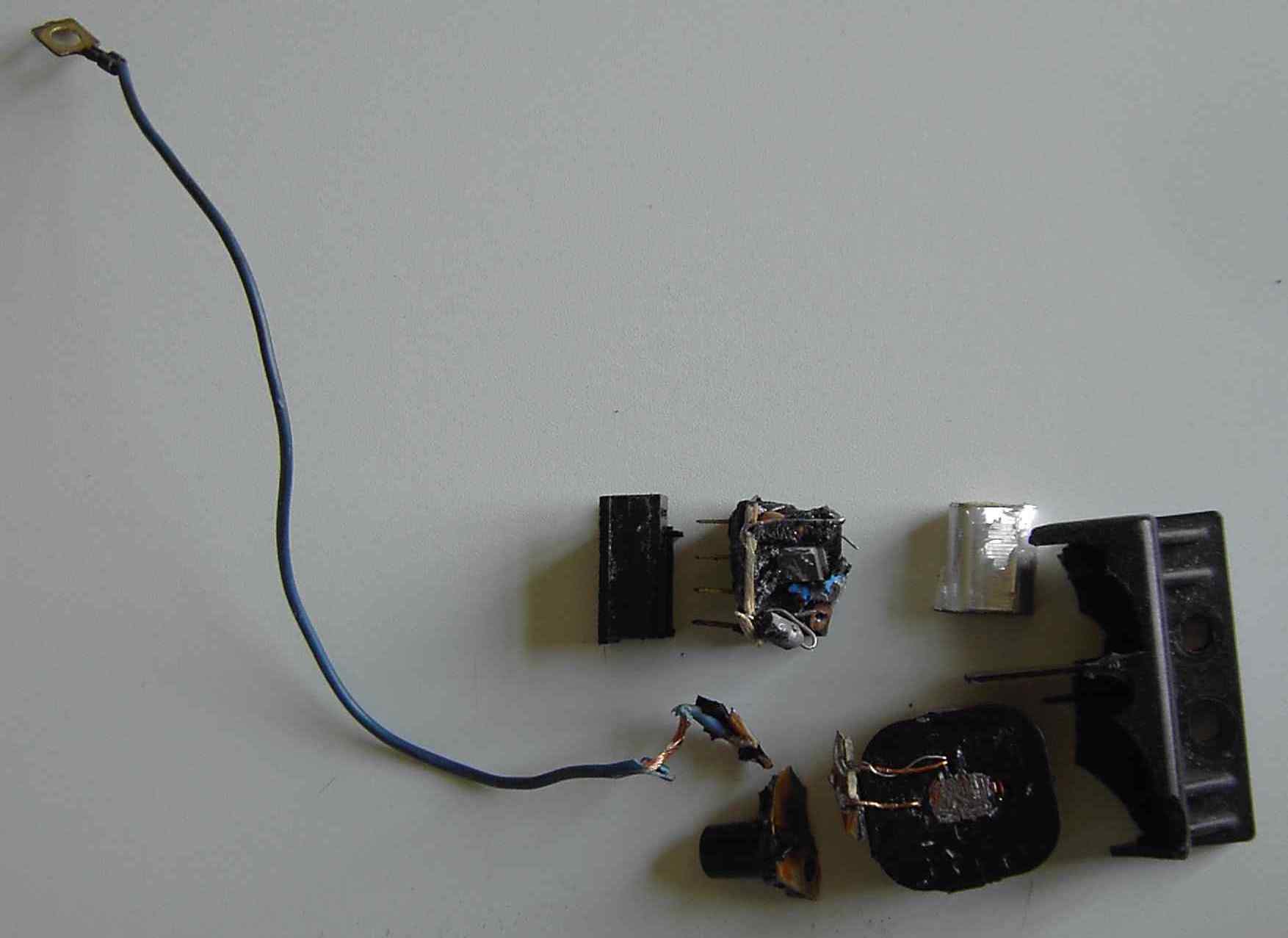
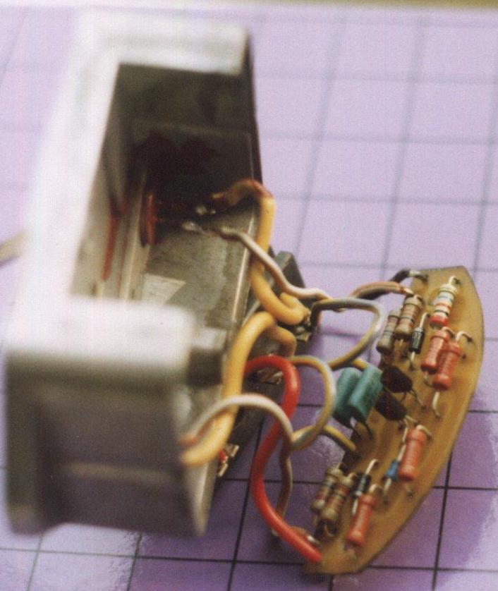
TRANSDUCERS, self-build, repair, replacement
Inside the transducers of the Morini ignition there is a small electronic
circuit and a coil. The circuit consists of some resistors, condensers, diodes
and a thyristor. This thyristor is an electronic switch, which has the same
function as the set of contacts of a conventional ignition. Below you will
find the circuit and a photo of a self-build transducer. Mind you, in case
you're planning to build such a transducer, you will have to add an external
6 V coil. (Best results came from a 6 V external coil for each transducer).
It is also possible to use the coil from the transducer of a Honda 250/400N.
In case of broken transducer(s) you can choose to build your own transducer.
You will save yourself a lot of money that way, or you can buy brand-new transducer(s),
which are still available in Germany (see below).
 |
|
The electronic circuit of a 1-st series of transducer.
Mind you: an external coil should be connected to such a
self-made transducer (see above). |
The self-made transducer (without external coil) on
both sides. |
Build your own transducers:
Volker Sachse (see http://www.italoclassicbikes.de/) from Germany has sent me the following information in a PDF file:
- new professional layout for a circuit board. Mind you, the layout shows the bottom of the circuit board, the copper tracks !!
- layout with the electronic components drawn in again, you are looking to the bottom of the circuit board !
- the circuit;
- list of necessary parts.
Open the file here |
You will need Acrobat Reader to open the file. In case you don't have it, get it for free at:
 |
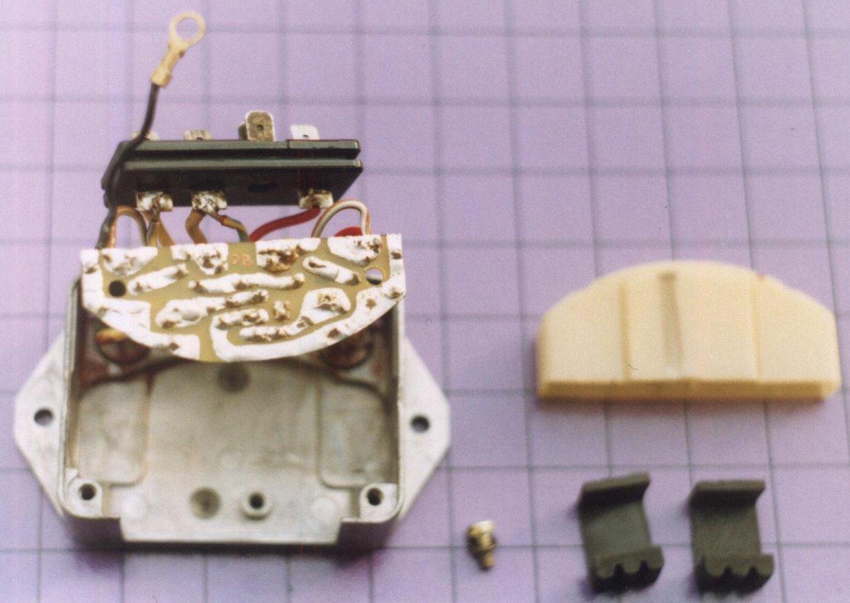
Repair:
At the bottom of each transducer you will find a dark-red potting substance. You have to carefully remove this. You can
use "dimethylsulfoxid" (C2H5OS) and mix it 1:1 with "aceton" (nailvarnish remover)
(C3H6O). This mix will solve the potting substance. It is a time-consuming process and you have to be
careful you don't destroy the contains of the box and the housing. When a transducer is broken, it is mostly the coil or the
thyristor that needs replacing.
 |
|
 |
this is the coil inside the transducer |
|
contains of the transducer |
Replacement:
- Make sure the replacement transducer is of the correct type (see table above).
- Try a breaker, or a Morini dealer or supplier.
- See the dealer section of our "Linkpage"
- When you're in Britain, try Mdina Italia
- contact George Lane (tel. + 44 (0)1252 816 817).
- In the US, contact Herdan, the
former importer in Port Clinton (tel. +1 610 562 3155).
- Another source for brand-new transducers can be found at Morini specialist Tremezzo.
 |
 |
 |
 |
 |
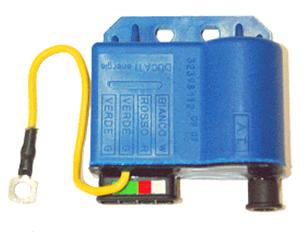
This Ducati 32398112 is produced by the Italian company
Fodone.
Originally for Piaggio and Lambretta scooters, but according to
the German Morini forum this transducer is suitable to replace transducer 323921 (square black). Ignition timing, the
advance curve should be correct, according to the Germans. That is the reason that
Tremezzo sells these as a replacement for the 323921. |
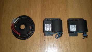
New transducers and pickup from the
Italian Nuovaray.
Price in 2011 was 260 Euro for the complete set. In their
catalogue you also can find
replacement for the black pickup, magnets and some models rectifiers.
Note 1. On this Nuovaray model NR-C30 there is no connection for the electronic
rev. counter. This is the replacement for the 3rd generation (323982) transducers (black pickup and mechanical rev. counter).
Note 2. Nuovaray has got the NR-C31 as a replacement for the 323921. |
This is the NR-C30 of NuovaRay to replace the 323982. In the NuovaRay catalogue you will find it under
NR-C30 (nr. 32.3982). The webmaster can confirm that this model works perfectly on the 350. Attention: it has no connection for an
electronic rev. counter. Correct for this transducer, as it is meant for the later 350cc bikes with a mechanical rev. counter. Price
50 Euro's each, excl. postage from Italy. |
The red transducer as shown above (type 32398710) was previously available as a replacement
for Moto Morini transducers. You can still find them at Ebay, or similar sites, but meanwhile much better replacement is possible.
The black pickup shown is an original part. |
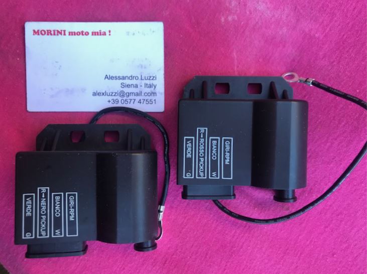
Transducers (external ignition coils) for Moto Morini models 250V, 350, 500
One of the critical elements for the proper operation of Morini engines with electronic ignition are the transducers. In the market there are
aftermarket transducers available for the operation of the Morini engines. There are some reserves on the performance of some of these items,
because they were originally designed to operate on 2-stroke engines. Therefore they perform following an ignition curve that is not ideal for
4-stroke engines. In addition these aftermarket transducers are not provided with the output for the electronic rev counter and this often
imposes to renounce to the use of the rev counter. The company Luzzi (in Sienna/Italy), specialized in the sale of spare parts for historical
Morini bikes, in cooperation with specialized engineers has designed and produced transducers with the following performances:
- Fully interchangeable with the original transducers,
- Power equivalent to the power of the original transducers,
- Output for electronic rev counter,
- Bidirectional protection on the rev counter output to avoid reciprocal interferences and damages between rev counter and transducer,
- Solid housing with practical connectors.
The new/improved transducers are available for both the red as well as for the black pick-up. |
For your information, on the website:
http://www.motelek.net/andere/cdi/ you will find a long list of
non-Moto Morini transducers with their electric diagrams. Be careful, the transducers on the motelek.net website are not meant
to install on your Moto Morini. I have only published that website to have a look at the many differences between transducers.
Another website on the Moto Morini ignition of the 350/500cc models.
Tip: use Google translate for an English version.
|
Alternative systems
There are professional alternative systems available, like the full-electronic ignitions of the makes:
- Lucas Rita. Follow the link to a new sub-page, written by Kieran,
who successfully installed a Lucas Rita set. Kieran sums up the pro's and con's of this system.
- Boyer Bransden. Follow this link to a new sub-page written by
Lars. He gives a good description on how to succesfully install a Boyer Bransden set on a Moto Morini. Boyer Bransden
have both an analog as well as a digital ignition available. Lars installed the analogue system, but there is also
information on the digital Boyer Bransden.
- Vape (former Power Dynamo, also known as
"MZ-b" Berlin) produces alternative ignition systems for a wide range of classic motorbikes.
They also have a system for the Morini 3˝
and also for the
Morini 175cc singles like the 175 GT,
175 Tresette and 175 Turismo. Also available a system for the
Corsaro 125/150cc.
-
Digital ignition for the 350/500 from Sachse electronics. Also available for the 250cc
- Nuovaray
many parts for the original ignition like transducers, rotors, pickup's etc.
Please note: the URL for the vintage catalogue for Nuovaray producs keeps changing. If the link does not work,
1) go to www.nuovaray.com, 2) choose English, 3) Products, 4) Automotive motorcycle parts, 5) vintage.
- Luzzi (see picture rhs above), can be contacted by e-mail or phone (speaks/writes excellent English).
- Horse Power Ignition for the 125/250/350/500cc
models. Also sets available for the 175cc singels and Corsaro 125/150cc.
- Catalogue Societá Generale Ricambi (europa) p.A
with transducers and rectifiers for models 125H, 250T, Dart, Excalibur, Coguaro, New York.
- Also a catalogue of Societá Generale Ricambi
(europa) p.A, but in French
with transducers and rectifiers for models 125H, 250T, Dart, Excalibut, Coguaro, New York.
|
NEW PICK-UP'S (RED OR BLACK) AVAILABLE IN GERMANY
Marcus Heilig from Germany has developed a new pickup for the Morini V-twin
models. Replacements for both red and black pickup are available! With these new pickups it is possible to set the timing
of front and rear cylinder seperately. This is an improvement compared to the original ones made by Ducati Elettrotecnica.
See Marcus' website (in German, but with excellent photo's
of the prototypes & ready version pickup and even a film of the testing).
|
IN-DEPTH TECHNICAL INFORMATION ON THE OEM PICK-UP AND IGNITION CURVE
- In depth technical article in German on Morini pick-up operation, design, parameters written by Franz Grabowski.
Also contains info on ignition curve and few hints how >to improve the Morini ignition
Information is available in .pdf format.
- An article treating on ignition curve, written by Gunnar Lerch.
German version .pdf format
English version .pdf format (translation from German to English by Peter
Cloer and Gunnar Lerch).
To get Acrobat Reader to read the .pdf files, follow this link
|
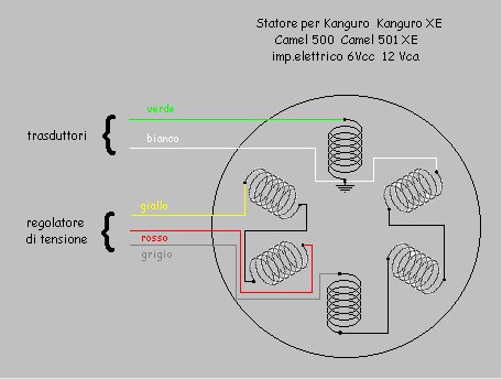
HOW TO REWIND THE ALTERNATOR
To rewind the 12 Volt, 100 Watt alternator look at this schematic
diagram for number and direction of inner and outer windings. Wire used is 0.8mm
pu-insulated copperwire. The diagram is drawn by Lars Bendsen from Denmark.
Note 1: later models with an electric starter have a "heavier" alternator (180 Watt?);
Note 2: to rewind the seperate ignition coil
follow this link to a sub-page. (The ignition coil is the yellow one shown on the photo's on this page).
Note 3: the offroad models Kanguro and Camel have a different alternator of both 12V (directly to headlight)
and 6V (rest of the bike). The conversion of the 6V alternator of the Camel/Kanguro models can be done as described
by Werner Wilhelmi in this article.
|
 |
 |
The 6V/12V combined alternator
as on the Camel and Kanguro ... |
... and a 12V alternator of later models. On earlier alternators there is no seperate earthwire
(white). This particular alternator could well be from an Excalibur 350/501, as the red pick-up wire is missing (Kokusan
ignition!) |
|
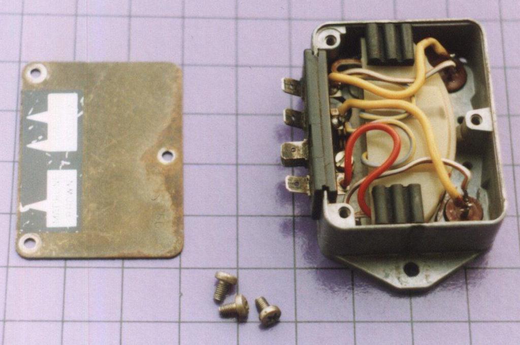
ELECTRONIC RECTIFIER
In case the electronic rectifier on your Moto Morini has broken, you can find some information on this part below. Soon a
list of electronic components will be added. There are two different rectifiers known used by Moto Morini for the V-twin
models (and singles). Below you can find information on the 12 Volt version used by Morini BEFORE the introduction of the
e-start motorbikes.
All I have available on the rectifier for the e-start models is a hand-drawn
circuit.
 |
 |
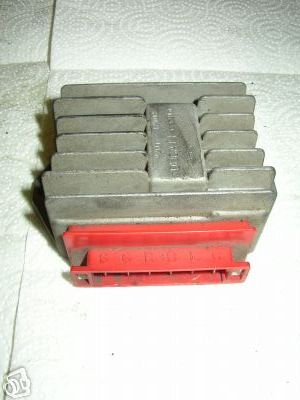 |
The original rectifier on the pre-electric start models. |
The 2nd model for the e-start models |
 |
 |
 |
|
Both sides of the circuit
board, with the electronic
components drawn in. |
The circuit of the rectifier for the e-start models. |
| Volker Sachse (see http://www.italoclassicbikes.de/)has built a Morini rectifier,
see circuit, etc.. Detailed photo's will follow. After download, the file can be opened with Adobe Acrobat Reader.
See the link elswhere on this page to get free Acrobat Reader. |
| back to index page |
|
|
|
|
|